Z Rotation Cubing
Projecting 3D on 2D
Rotation angle specified as a real-valued scalar. The rotation angle is positive if the rotation is in the counter-clockwise direction when viewed by an observer looking along the z-axis towards the origin. Angle units are in degrees. Data Types: double.

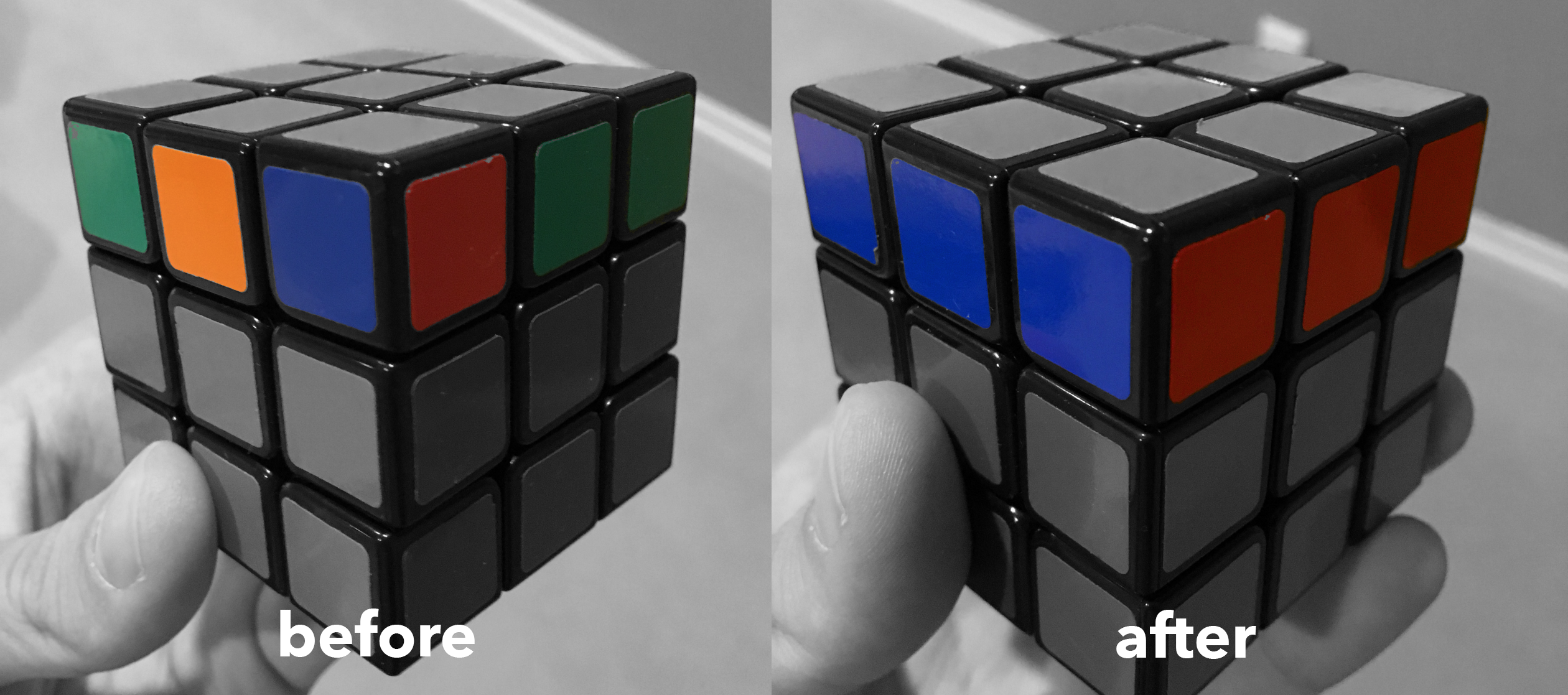
- Advanced Notation. For the intermediate and advanced methods, other letters for notation will be used. These include: x for rotating the cube like an R; y for rotating the cube like a U; z for rotating the cube like an F; M for the layer between L and R; E for the layer between U and D; S for the layer between F and B; E and S are used very rarely, as they are quite awkward to perform and can.
- CFOP Method Algorithms: QiYi Valk 3: http.
A point in a three-dimensional coordinate system can be represented by a (3times 1) matrix. When modelling three dimensions on a two-dimensional computer screen, you must project each point to 2D. After the projection, each point is represented by a (2times 1) matrix.

If we assume that the (z)-axes (or the third base vector) is pointing from the computer screen, then the screen is a projection on the (xy)-plane.
The projection matrix (mathbf{P}) must map the matrix (mathbf{v}=left( begin{array}{} abc end{array}right)) onto a matrix (mathbf{w}=left( begin{array}{} ab end{array}right)). This can be achieved by letting
[mathbf{P}=left( begin{array}{} 1 & 0 & 00 & 1 & 0 end{array}right)]
Then let (mathbf{w}=mathbf{P}mathbf{v}).
Matrix as a visual point
In GeoGebra, matrices are represented by lists. A (2times 1) matrix is not shown in the drawing pad.
If you want to show a matrix (mathbf{matrix1}=binom{2}{1}) as a point, you must use the matrix elements as coordinates for a new point. You retrieve an element of a matrix by using the command Element[<matrix>, <row>, <column>].
To show a (2times 1)-matrix (mathbf{w}) as a point (A), you write:
Exercise 1
Make three sliders to represent the matrix elements (v_x, v_y, v_z) of a matrix (mathbf{v}).
Create the matrix (mathbf{v}) by using the spreadsheet or by entering it as a list in the input bar:
v={{v_x},{v_y},{v_z}}Create the projection matrix (mathbf{P}).
Create the projected matrix (mathbf{w}=mathbf{P}mathbf{v}) in the input bar:
w=P vCreate a point A, having the elements of (mathbf{w}) as coordinates.
Change the sliders. When changing the (v_z)-slider, nothing should happen with the point (A).
The rotations
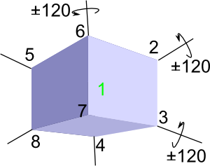
If the z-axes points from the screen, and if you rotate the base vectors by an angle (alpha) around the z-axes, you get the rotated vectors as in the picture below.
The third base vector, that is parallel to the z-axes, does not change.
The rotation matrix (mathbf{T_z}) for rotation around the z-axes is:
Z Rotation Cubing
[mathbf{T_z}=left( begin{array}{ccc} cos alpha & -sin alpha & 0 sin alpha & cos alpha & 0 0 & 0 & 1 end{array} right) ]
In a similar way you can find the rotation matrices for rotation around the x- and the y-axes.
[mathbf{T_x}=left( begin{array}{ccc} 1 & 0 & 0 0 & cos alpha & -sin alpha 0 & sin alpha & cos alpha end{array} right) ]
[mathbf{T_y}=left( begin{array}{ccc} cos alpha & 0 & sin alpha 0 & 1 & 0 -sin alpha & 0 & cos alpha end{array} right) ]
Exercise 2
Enter three sliders representing the three rotation angles, one angle per axes/base vector.
Enter three rotation matrices, one matrix for each angle.
Instead of just projecting the matrix (mathbf{v}) to 2D, it must now be rotated before the projection. Change the definition of the matrix (mathbf{w}) from (mathbf{w}=mathbf{Pv}) to (mathbf{w}=mathbf{PT_xT_yT_zv})
The Vertices of the Cube
The eight vertices of the cube must be transformed in the same way as the matrix v. The vertices must be rotated, projected, and represented by visual points. Since the same operations must be applied eight times, it is easiest to use the spreadsheet.
Let the cube have its vertices in at the coordinates (1,1,1), (1,-1,1), (-1,1,1), (-1,-1,1), (1,1,-1), (1,-1,-1), (-1,1,-1) and (-1,-1,-1).
Z Rotation Cubing
One way to do the operations is to enter the coordinates in the spreadsheet and then:
Make a matrix of the coordinates of one point, then make relative copies of that matrix.
Perform the transformations on one matrix, then make relative copies of the result.
Make a point of one transformed matrix, then make relative copies of the point.
The operations are done in column A in the picture below. The relative copies are made by dragging to the right.
Rotate the points to fill in the sides of the cube by using the Polygon tool.
It is of course possible to use other coordinates for the vertices of the cube.

Using the same spreadsheet, you can now rotate other 3D objects and project them on 2D.